
GLSL Tutorial – Directional Lights per Vertex I
| Prev: Lighting | Next: Dir Lights per Vertex II |
 To compute the intensity of the reflected light, assuming a Lambertian diffuse reflection model, we compute the cosine between the vector pointing towards the light (L) and the normal vector (N). The cosine can be computed based on the dot product:
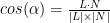
Hence, assuming that vectors L and N are normalised, we can compute the cosine as the dot product between these two vectors. The result of the dot product then gets multiplied by the diffuse component of the object’s material, Kd. The lighting equation is:

In order to perform operations with multiple vectors, these must be in the same space. There are typically many spaces where we can work on. Local space, world space, and camera space, are the most common to work with vectors. Regarding lighting, we can define the light’s direction, and other properties, in any of these spaces. When we define a light in local, or model, space, it works as if the light is attached to the object, like the light bulb in a desk lamp, as in Luxo Jr. from Pixar. Defining a light in world space works as if the light is placed in the 3D world we are building, regardless of the camera or any object. Working with lights in camera space means that the light is defined relatively to the camera (the camera in this space is placed at the origin, looking down on the negative Z axis). Whenever the camera moves, the light follows. A miner’s helmet lamp is an example of such light, if we consider the eyes of the miner to be the camera.
For shaders to work with multiple lights, potentially in multiple spaces, it makes life easier for the shader programmer to assume that all lights are defined in the same space. Camera space is a common option. This implies pre-transforming the light’s properties from the space in which they are defined to camera space.
Hence, we either transform the lights properties, such as direction and position, in the application and send these values in camera space to the shader, or we’ll have to consider where the light has been defined and transform those properties accordingly inside the shader.
If the light is defined in world space, sending it as is to the shader implies that it must be transformed inside the shader to camera space, i.e. the vector representing the light’s direction (actually the vector points towards the light) must be transformed by the view matrix. Another option is to assume that the application already provides this data in camera space. When considering a light in world space the light’s properties are commonly constant at least during the duration of a frame, and sometimes during the whole application. This second approach implies a one time computation, at most per frame, on the application side vs. performing the same transformation for each vertex, which can be in a very large number. In here we’re going to adopt the second approach, the application providing the transformed light’s properties to the shader. As mentioned before, the vectors must be normalised in order to simplify the cosine computation, hence the application will also be responsible for the normalisation of the light’s vectors.
This is pretty simple if using the VSMathLib and VSShaderLib. Assuming the light’s direction is stored in a variable named l_dir inside a block named Lights, the following snippet at the beginning of the rendering function should do the trick.
// load the identity matrix
vsml->loadIdentity(VSMathLib::VIEW);
// set camera
vsml->lookAt(camX, camY, camZ, 0,0,0, 0,1,0);

float lightDir[4] = {1.0f, 1.0f, 1.0f, 0.0f}; // light dir in world space
float res[4]; // here we'll store the light's direction in camera space
// transform light to camera space, normalise it, and send to GLSL
vsml->multMatrixPoint(VSMathLib::VIEW, lightDir, res);
vsml->normalize(res);
shader.setBlockUniform("Lights", "l_dir", res);
Assuming that we’re going to work in camera space, the normals must be transformed from local space to camera space. We are going to use the normal matrix for this purpose.
In all shaders, the matrix m_pvm (mat4) stands for a matrix that is computed as the multiplication of the projection, view, and model matrices. The normal matrix is referred to as m_normal (mat3).
The vertex shader must receive as inputs the position and normal of each vertex, and output the computed colour. We also need the above mentioned matrices and the direction towards the light, lightDir (vec4), and the diffuse colour of the material, diffuse (vec4).
Although it may look excessive in this first example, we’re going to use uniform blocks for the matrices, material, and light properties as these will help to keep the code clean later on.
We are also going to use blocks for intershader communication.
The vertex shader could be written as follows:
#version 330

layout (std140) uniform Matrices {
	mat4 m_pvm;
	mat3 m_normal;
};

layout (std140) uniform Materials {
	vec4 diffuse;
};

layout (std140) uniform Lights {
	vec3 l_dir;	   // camera space
};

in vec4 position;	// local space
in vec3 normal;		// local space

// the data to be sent to the fragment shader
out Data {
	vec4 color;
} DataOut;

void main () {
	// transform normal to camera space and normalize it
	vec3 n = normalize(m_normal * normal);

	// compute the intensity as the dot product
	// the max prevents negative intensity values
	float intensity = max(dot(n, l_dir), 0.0);

	// Compute the color per vertex
	DataOut.color = intensity * diffuse;

	// transform the vertex coordinates
	gl_Position = m_pvm * position;
}
The output colour will be interpolated per fragment, based on the gl_Position values, and the resulting per fragment value will be fed to the fragment shader. This shader only has to output the received colour.
#version 330

in Data {
	vec4 color;
} DataIn;

out vec4 outputF;

void main() {

	outputF = DataIn.color;
}
The following image shows this shaders in action:

The lit surfaces look nicely curved, but the surfaces facing away from the light are completely dark. A simplistic solution to overcome that is to add a little bit of ambient light. A simple implementation adds the ambient term to the resulting colour.

The ambient term is commonly a scaled down version of the diffuse term. In the figure below the ambient term is actually a quarter of the diffuse term. If this is the true for all materials then another option to compute the colour is as follows:

Depending on the material’s ambient setting, this can create very bright pictures because in the areas where the model is lit the ambient colour will also be added. Another option is to compute the maximum between both components. Under this approach, the ambient term can be seen as threshold providing a minimum level of lighting in those areas where the model isn’t lit.

The following images show how the above solutions look like in our case:

Figure: left: diffuse only; midlle: diffuse + ambient; right: max(diffuse, ambient)
In our shader we’ll go for the maximum. The vertex shader is very similar, the following shows only the relevant bits, with the differences highlighted:
layout (std140) uniform Materials {
	vec4 diffuse;
	vec4 ambient;
};

...

void main () {

	...

	// compute the color as the maximum between the two components
	DataOut.color = max(intensity * diffuse, ambient);

	...
}
The fragment shader is the same as before.
Next we’ll deal with the material’s specular term.
| Prev: Lighting | Next: Dir Lights per Vertex II |
Is there an example source file on how to use the shaders in this tutorial? Do I need to provide any input other than l_dir? It seems like I need to provide a lot of variables here and I don’t know what those consist of.
Yes, there is complete source code for all light types in the Lighting page of the tutorial