
GLSL Tutorial – Texture Coordinates
| Prev: Spotlights | Next: Texturing with Images |
Texture coordinates are commonly used to define how an image maps to a surface. However texture coordinates are not restricted to perform this mapping. Texture coordinates per se can be used to color a model. Here we will see a couple examples of how texture coordinates can be used on their own.
The first step is making the textures coordinates available to our shaders. Texture coordinates are just another vertex attribute, much like normals. Hence in the application we need to treat them as such, i.e. we need to add a buffer with the texture coordinates to the vertex array object that contains all the other models attributes (see this section for more details on attributes).
In the vertex shader we shall receive the texture coordinates as inputs, and commonly we simply copy them to an output variable. this variable will be received as input in the fragment shader, where we can use it for the purpose of our application.
The code below illustrates the process described above:
Vertex Shader
#version 330

uniform mat4 pvm;

in vec4 position;
in vec2 texCoord;

out vec2 texCoordV;

void main() {

	texCoordV = texCoord;
	gl_Position = pvm * position;
}
Fragment Shader
#version 330

in vec2 texCoordV;

out vec4 colorOut;

void main() {

colorOut = vec4(texCoord, 0.0, 0.0);
}
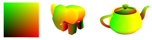
The output of these shaders displays texture coordinates as colors, showing how the texture mapping is defined in a model. For instance, the figure below shows a plane, an elephant, and the teapot, with their texture coordinates. Red will be used for the s coordinate, and green for the t coordinate. These shaders can be useful for debugging when texturing with an image provides unexpected results.
Playing with texture coordinates
Texture coordinates can also be used for some interesting effects. For instance, assume that we want to obtain a grid effect as shown in the image below:
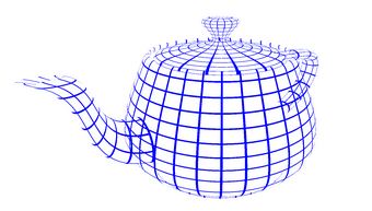
To achieve the above we are only painting certain pixels (in blue) and discarding the remaining pixels with the GLSL keyword discard. The density of the grid is defined by a multiplication factor applied to the texture coordinates. The fragment shader then selects only those pixels that have one of the texture coordinates with a fractional value below 0.1, painting these with blue color. This last value, 0.1, controls the width of the lines drawn.
The vertex shader is the same as above, only the fragment shader needs to be rewritten . Below we set the stripe multiplication factor to 8. Varying this value and the threshold alters the number of grid cells and their width, respectively.
#version 330

uniform int multiplicationFactor = 8;
uniform float threshold = 0.1;

in vec2 texCoordV;
out vec4 colorOut;

void main() {
	// multiplicationFactor scales the number of stripes
	vec2 t = texCoordV * multiplicationFactor ;

	// the threshold constant defines the with of the lines
	if (fract(t.s) < threshold  || fract(t.t) < threshold )
		colorOut = vec4(0.0, 0.0, 1.0, 1.0);
	else
		discard;
}
The discard keyword causes the fragment to be … discarded. This causes the shader to be stopped and nothing will be written in any of the buffers, both color and depth.
Another interesting example is to pick a color based on texture coordinates. For instance we can write a shader to paint stripes on an object. The shader will decide which color to use based on the fractional part of the texture coordinates. For instance when the fractional part of the s coordinate is lower than 0.5 the shader picks one color, otherwise the other color would be picked.
Again, only the fragment shader needs to be rewritten.
#version 330

uniform vec4 color1 = vec4(0.0, 0.0, 1.0, 1.0);
uniform vec4 color2 = vec4(1.0, 1.0, 0.5, 1.0);

uniform int multiplicationFactor = 8;

in vec2 texCoordV;

out vec4 outputF;

void main() {

	if (fract(texCoordV.s * multiplicationFactor) < 0.5)
		outputF = vec4(0.0, 0.0, 1.0, 1.0);
	else
		outputF = vec4(1.0, 1.0, 0.5, 1.0);
}
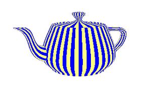
The result is severely aliased! This is because the coloring function we are using is a step function. To fix this we can use a function with smoother transitions as depicted in the figure below.
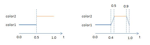
The fragment shader to implement this function is fairly simple. We are going to use GLSL mix function to do a linear interpolation on the colors as seen below. The first two parameters of the mix function are the colours to be mixed, and the last parameter specifies how the colours are going to be mixed, according to the following expression:

The fragment shader could be written as follows:
#version 330

uniform vec4 color1 = vec4(0.0, 0.0, 1.0, 1.0);
uniform vec4 color2 = vec4(1.0, 1.0, 0.5, 1.0);
in vec2 texCoordV;

out vec4 colorOut;

void main() {

	vec2 t = texCoordV * 8.0;

	float f = fract(t.s);

	if (f < 0.4)
		colorOut = color1;
	else if (f < 0.5)
		colorOut = mix(color1, color2, (f - 0.4)* 10.0) ;
	else if (f < 0.9)
		colorOut = color2;
	else
		colorOut = mix(color2, color1, (f - 0.9) * 10.0);
}
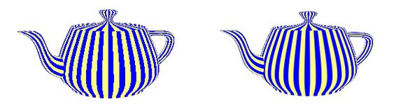
Observing the figure below, this later approach (right) is a clear improvement when compared to the previous one (left).
GLSL has a function that we can use to create the same effect: smoothstep. This function takes three arguments: a lower boundary (edge0), an upper boundary (edge1) and a value as a source for the interpolation.
Pseudo code:
if (x <= edge0)
    return 0.0;
else if x >= edge1
    return 1.0;
else {
    t = (x - edge0) / (edge1 - edge0);
    return 3.0*t^3 - 2.0*t^2;
}
Between edge0 and edge1, this function performs Hermite interpolation (smooth cubic curve) between 0 and 1.
Here are two examples of the resulting curves calling this function with different parameters:
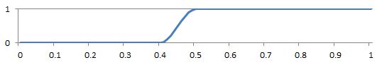
f = smoothstep(0.4, 0.5, x);
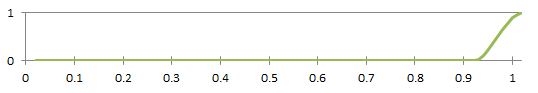
f = smoothstep(0.9, 1.0, x);
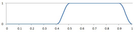
None of the above are what we are looking for, but when we combine them as follows, we get exactly what we want:
f = smoothstep(0.4, 0.5, t.s) - smoothstep(0.9, 1.0, t.s);
The result f could then be used as a parameter in the mix function to select the final color. The fragment shader above could be written as:
#version 330

uniform vec4 color1 = vec4(0.0, 0.0, 1.0, 1.0);
uniform vec4 color2 = vec4(1.0, 1.0, 0.5, 1.0);

uniform int multiplicationFactor = 8;

in vec2 texCoordV;
out vec4 outputF;

void main() {
	float x = fract(texCoordV.s * 8.0);
	float f = smoothstep(0.40, 0.5, x) - smoothstep(0.90, 1.0, x);
	outputF = mix(color2, color1, f);
}
Source code and a VS2010 solution can be found here.
| Prev: Spotlights | Next: Texturing with Images |