
GLSL Tutorial – Directional Lights per Vertex II
| Prev: Dir Lights per Vertex I | Next: Dir Lights per Pixel |
When we consider shiny materials we observe a bright spot depending on the camera and light’s direction, usually in a colour different from the diffuse colour. For instance an apple may be green, but the bright spot has the colour of the light. This bright spot, aka specular highlight, varies in size, being more sharp in metallic objects, and more blurred in plastics. The position and intensity of the specular highlight also varies with the position of the observer.
In most materials, the intensity of the reflected specular light is at its maximum in the direction of the reflection of L around N. The reflection vector can be computed as in the following diagram:

Figure: Computing the reflection vector
We know that both L and N are normalized, and cos(

The intensity of the specular highlight will have its maximum magnitude when the camera vector is aligned with the reflection vector. As the camera vector moves away from the reflected light vector, the intensity of the specular highlight will become dimmer.
Phong proposed that the intensity of the specular highlight could be computed as the cosine of the angle between the reflection vector and the eye vector, as depicted in the next figure.

Figure: Specular lighting vectors
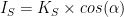
Phong’s specular term captures this in the following equation:
Blinn later proposed an alternative to the Phong equation using the half-vector. The half-vector is the vector that its half way between the light vector and the eye vector. The vectors are depicted in the following figure.

Figure: Half-Vector
Assuming that both vectors are normalized, the half-vector, H, is computed as

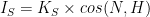
The cosine between the vector H and the normal vector, N, provides an alternative Phong’s original idea. Note that to use the dot product to compute the cosine the vector H must have been normalized previously. The equation with the half-vector is called the Blinn-Phong equation.
Applying these equations directly can cause the specular light to flood the scene, washing away all the other colours, as shown in the next figure:.

Figure: Applying the specular term
To prevent this flooding, and control the specular effect, Phong introduced another term, called shininess. The Blinn-Phong equation with the shininess term, s, is as follows:

The result of adding the shininess term can be observed in the following figure. For s = 1, we have the cosine curve. As s grows bigger, the curve gets steeper, essentially providing non zero values for the specular term in smaller and smaller intervals. On the other hand, if s goes below 1, then the curve gets wider, hence the specular term will affect more points.

Figure 8. Applying the shininess term
Getting back to our teapot, when s = 100 we get the following result:

Figure: Teapot with specular term and shininess set to 100
Now, let’s see how to implement this. We need two more uniforms in our Materials block, the specular colour, and the shininess term.
Inside the main function we have to compute the eye vector, and the half-vector. To compute the eye vector we have to transform the vertex’s position with the View Model matrix (m_viewModel in the shader) to get it in Camera space.
Then, we compute the dot product between the normalized half-vector and the normal to determine the specular intensity. We use the power function with the specular intensity and the shininess term, and finally multiply it by the specular colour of the material. The computed specular colour is then added to the final colour.
The following vertex shader implements these ideas:
#version 330

layout (std140) uniform Matrices {
	mat4 m_pvm;
	mat4 m_viewModel;
	mat3 m_normal;
};

layout (std140) uniform Materials {
	vec4 diffuse;
	vec4 ambient;
	vec4 specular;
	float shininess;
};

layout (std140) uniform Lights {
	vec3 l_dir;	   // camera space
};

in vec4 position;	// local space
in vec3 normal;		// local space

// the data to be sent to the fragment shader
out Data {
	vec4 color;
} DataOut;

void main () {

	// set the specular term initially to black
	vec4 spec = vec4(0.0);

	vec3 n = normalize(m_normal * normal);

	float intensity = max(dot(n, l_dir), 0.0);

	// if the vertex is lit compute the specular term
	if (intensity > 0.0) {
		// compute position in camera space
		vec3 pos = vec3(m_viewModel * position);
		// compute eye vector and normalize it
		vec3 eye = normalize(-pos);
		// compute the half vector
		vec3 h = normalize(l_dir + eye);

		// compute the specular term into spec
		float intSpec = max(dot(h,n), 0.0);
		spec = specular * pow(intSpec, shininess);
	}
	// add the specular term
	DataOut.color = max(intensity *  diffuse + spec, ambient);

	gl_Position = m_pvm * position;
}
The fragment shader is the same as in the previous section.
The end result of this shader applied to a torus is:

Hummm, it does look awful! The specular component tells a lot about the underlying mesh representing the torus. This is due to the interpolation that occurs based on the colour. To improve this result we either create a very dense mesh, or we use per pixel lighting, as described in the next section.
Note that the dense mesh only solves the problem when we have a triangle per pixel which is not practical, as a priori we have no knowledge as to how many pixels are covered by each triangle, and such a number of triangles might prove infeasible for real time rendering.
| Prev: Dir Lights per Vertex I | Next: Dir Lights per Pixel |