This website uses cookies to improve your experience while you navigate through the website. Out of these, the cookies that are categorized as necessary are stored on your browser as they are essential for the working of basic functionalities of the website. We also use third-party cookies that help us analyze and understand how you use this website. These cookies will be stored in your browser only with your consent. You also have the option to opt-out of these cookies. But opting out of some of these cookies may affect your browsing experience.
Necessary cookies are absolutely essential for the website to function properly. This category only includes cookies that ensures basic functionalities and security features of the website. These cookies do not store any personal information.
Any cookies that may not be particularly necessary for the website to function and is used specifically to collect user personal data via analytics, ads, other embedded contents are termed as non-necessary cookies. It is mandatory to procure user consent prior to running these cookies on your website.
Lighting Nodes
Up until know the worlds you've seen in this tutorial have been lit by a special light, the headlight. This light is created by your browser and it is attached to the current viewpoint. This light always points to where you're looking at. It is like if you had a light attached to your head. This light can be turned on or off using the browsers options or with the NavigationInfo node.
VRML supports three additional types of lights. They are:
When using a Directional Light the light rays are all parallel. This light has no defined location, only a direction. It is as if the light is far, far away from your world.
A Point Light is a light, placed in your world, which brightens everything around it, the light rays go in all directions from the light's location. Think of the sun for instance.
A Spot Light is a ... spotlight. This type of light creates a cone of light.
Further informationspecific to each type of light is provided in the links above. However if you're new to lighting in VRML then the following should be of some use to help you understand how it is done in VRML. Note: in all the figures bellow the headlight is turned off.
Light Reflection
In theory when light rays hit an object the object may reflect the light rays depending on its color and the color of the light. Light reflection depends on the properties of the object being lit. Surely you have seen 3D realistic static images where this effect is present.
However computing light reflection on the fly is hard work. In order to display 3D worlds interactively some short cuts had to done in order for the action to be as smooth as possible. Therefore there is no reflected light in VRML, only direct light is available. This means that if an object is not in the path of the light rays from any of the lights placed in your world it will remain dark.
As a replacement for light reflectiont, the lights in VRML have a field called ambientIntensity. This field controls how much the light contributes to the overall world lighting. With high values for ambientIntensity the world will be a brighter place. Although a crude replacement it can add some realism to yuor world.
Light Attenuation and Scope
Another real world lighting effect is that the light gradually grows weaker with distance. In VRML this feature is implemented. With the field attenuation you can specify how the light drops off as distance increases.
So how does one control lighting attenuation with Directional Light? This type of light only iluminates the objects which are placed within the group where the light is defined. On the other hand, the Point Light and Spot Light are independent of their position within the file, i.e. they're lighting effect is not restricted to the group in which they are defined.
Shadows
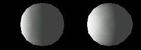
Look at the following figure. In it there is a Point Light placed at the left, and two Spheres in the right. The Point Light and the center of the Spheres are colinear.
According to the text above the left sphere should block the light rays from reaching the sphere on the right. However from the figure it is clear that this is not happening. The reason is that shadows do not exist in VRML. The computational load to compute shadows is too heavy to display 3D graphics on the fly.
So how does one create shadows? You could create them manually, for instance in the figure above the right sphere could be defined darker than the left sphere simulating shadowing, however this approach is not realistic for anything but very small models. The only approach to block light is to define the objects which are not supposed to be lit by a particular light outside the group where the light is defined, however, as mentioned before, grouping nodes only have effect on Directional Lights.
Basically there is no way out, you're stuck with a shadowless world, unless you're a real perfectionist you're up to some real hard work.
Lighting Flat Surfaces
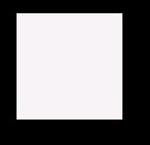
Consider the following figure. In it a Spot Light is aimed at the center of a cubic Box and the cube's face is inside the cone of light defined by the Spot light.
So far so good, the cube's face is fully lit as expected. Now consider the next figure. In it a spot light is also aimed at the cube's face but the light cone's intersction with the cube's face is a circunference which is totally inside the cube's face, i.e. none of the vertices of the cube's face are inside the cone of light.
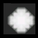
The cube's face is totally dark, why? Let's see another figure which may shed some light into this obscureness. In this next figure a spot light is aimed at the top right vertex of the cube. The cone of light does not contain any other vertex of the cube's face.
Again something is wrong, there should be a circular lighter area in the cube, and instead there is a linear one.
In VRML the light reflection of a flat surface is computed based on the average amount of light which reaches each vertex of the face. So in the first figure we had all vertices equally lit and the face is evenly lit. On the second figure none of the vertices were lit, therefore the face was dark.
The third figure has only one vertex lit, the top right one. Light along the right edge of the face is computed as the average between the top right vertex, which is lit, and the bottom right vertex, which is not lit, therefore the face becomes progressivelly darker as we move from the top right vertex to the bottom right vertex. Similar reasoning can be applied between the top right vertex and the top left vertex, as well as between the top right vertex and the bottom left vertex.
Now look at the next figure.
Now, things are getting better, OK you don't have a circular light inside the shape but at least the light doesn't lit the whole shape. The trick is to define either an IndexedFaceSet or a flat Elevation Grid. Using any of these shapes one can create a mesh, i.e. instead of defining a flat face using just the outer vertices, a mesh is created using small faces to construct the original larger face. As the faces which build up the mesh grow smaller, the light effect will get closer to a circle. This process, while providing more realism in the light effects, does have the disadvantage that more faces need to be drawn, therefore slowing down the display of the world. There is no rule of thumb to say when a performance problem will occur, you just have to try and use meshes of different granularity, i.e. varying the number of the small faces that make up the mesh, and see how performance is affected.
Colored Lights
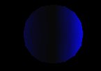
Color can be applied to lights as well as shapes. You can have blue lights, red lights, brown lights, just pick a color. However there is a detail that you should be aware of.
In the example above there is a blue sphere and a Spot Light to its right, right? Well, almost. There is also a red Spot light on the left side of the sphere and pointing at it. Yet no traces can be seen from this red light, why? The answer is simple, a blue sphere can only reflect blue light, and as there is absolutely no blue light in a red light the sphere remains black.
In the real world pointing a red light to a blue object wouldn't result in total darkness, but in the real world there is nothing like true red light, and true blue objects. All lights and objects in the so called real world have a mixture of colors. When we say that an object is blue we are saying that its stronger color is blue, and not that it doesn't contain any amount of any other color. In computer models true colors do exist though, so be aware.
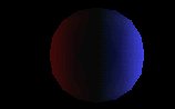
One possible fixture to this 'problem' is to avoid defining true colors. For instance, instead of defining blue as 0 0 1 in the RGB model which means true blue, define blue as 0.3 0.3 1, i.e. all colors are present altough there is a predominant color. The following figure has a sphere defined with this later 'blue'.
The sphere remains blue when lit by a white spot light, but now a tenuous effect from the red light is visible. Note however that defining colored lights in this way doesn't work in the same way. See for example the following figure in which the red light was replaced by a light whose coloring is defined in RGB by 1 0.3 0.3.
The effect of this new red light is not red at all! This is because only the blue part of the red light is reflected. The light effect from the light on the left is dimmer than the one from the right because the later has more blue light than the former.
Shapes Unlit
If the material field in the Appearance node is NULL or not specified then the associated geometry in the Shape node is not lit. If you don't want to specify a material you can always define the material field as: material Material { }
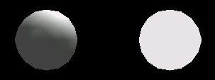
In the following figure a Point light is placed above two Spheres. Note however that while the left sphere is lit correctly, the right one is not affected by the point light.
The reason why the right sphere doesn't react to light is because the material field is undefined in the Appearance node of the shape.