Error 404 - Not Found
Sorry, the page that you are looking for does not exist.
 |
|||||||||||||||||||||||||||||||||||||||||||
|
VRML Script Tutorial Full list VRML Interactive Tutorial
Introduction
Hierarchical Node Structures
Defining and Instancing Nodes Defining Levels of Detail Events in VRML
|
 Lighthouse3d.comMostly about 3D graphics
Error 404 - Not FoundSorry, the page that you are looking for does not exist.
|
||||||||||||||||||||||||||||||||||||||||||
|
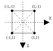
Note the Z axis orientation, the Z axis is positive downwards, not upwards. In 3D, using the default View Point this means that points closer to you have a higher Z value than points further away.
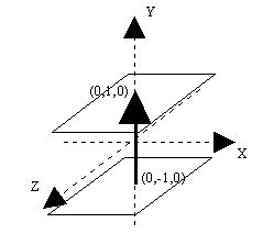
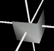
Another concept needed in an extrusion is the spine. The spine defines the path that the cross section will travel to create the shape. In the above example, trying to build a cube, one could start with the cross section at (0,-1,0) and move it upwards to (0,1,0). The following figures shows this spine for the cube, and the respective path for the cross section.
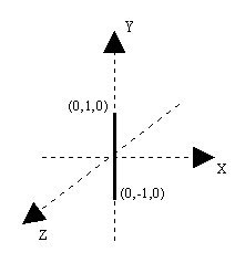
The spine in the above figure is defined by two points, (0,-1,0) and (0,1,0). The list of steps that the browser does to draw an extruded shape with two spine points are:
Source code for the above figure (without the axes)
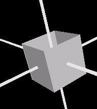
Notice that you can only see two sides of the cube, the ones that face you. This is because the field solid is set to TRUE by default. Setting this field to false yields the following result
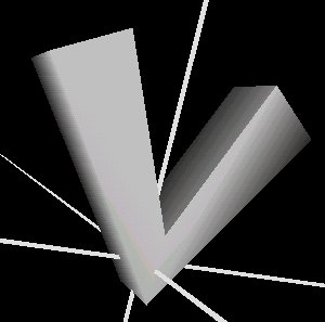
In the above examples the spine had only two points. That is the simplest spine you can have. However there is nothing preventing you from having more spine points, for example to draw a V shape, or even something more complicated.
The principle is always the same however there is something which deserves to be mentioned. As mentioned before, when using a two point spine, the cross section is oriented so that the Y axis coincides with the direction defined by the two spine points. When using more spine points this is only valid for the first spine point. The remaining spine points behave slightly differently.
The second and subsequent spine points orient the cross section so that is perpendicular to the tangent of the spine. The following figure, presented in 2D for simplicity reasons, shows the cross section orientation in a 3 point spine.
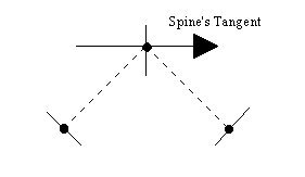
The points in the figure are the spine points. The dotted lines show the path defined by the spine. At each spine point the cross section's orientation is presented. Note that the cross section's orientation for the second point is perpendicular to the spine's tangent.
A V shaped spine, defined by the points: (3,5,0), (0,0,0), (-3,5,0), with the square cross section produces the following result:
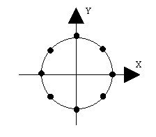
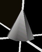
The cross section is defined by the following points: (-1,0), (0,0), (-2,-1), (-1,0). Note that the cross section repeats the first point, if you don't do that then you may end up with a non-solid shape. The spine is defined by selecting eight equally spread points in a unitary circle. The following figure depicts the cross section (note that the Z axis points downwards), and a circular spine defined in the XY plane.
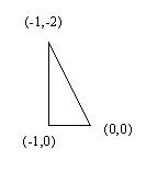
Please take notice of the cross section points. The point (0,0) is the point that coincides with the spine's point. The end result is the following figure:
Source code for the example above (without the axes):
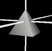
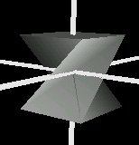
Wait, there's still more, you can scale and orient the cross section for each spine point specified. In the cube example presented above, you can scale the cross section for the second spine point by (0,0), thereby reducing it to a point, to obtain a pyramid as in the following figure.
When using the field scale you either specify one scale for the whole shape, or a list of scale factors for each spine point ( note that scales are provided in 2D because they relate to the cross section).
Source code for the above figure (without the axes)
Similarly to the scale field, when using the field orientation you either specify one orientation for the whole shape, or a list of orientation factors for each spine point. Orientations require four values each: three to define the axis of rotation and one to define the angle.
Source code for the above figure (without the axes)
The convex field specifies if the cross section is convex or not. When presented with concave cross sections, the browser splits the cross section into smaller convex cross sections. This is a time consuming task. If you are sure that the cross section is convex then setting this field to TRUE tells the browser not to worry splitting the cross section therefore saving time.
The creaseAngle specifies an angle threshold. If two adjacent faces make an angle bigger than the creaseAngle then you'll see clearly where the two faces meet, the edge linking the two faces is sharp. Otherwise the edge linking the two faces will be smooth.